
How to Remove a Stripped Screw From Metal
Remove a Stripped Screw From Metal. Practical removal sequence that protects the surrounding material.
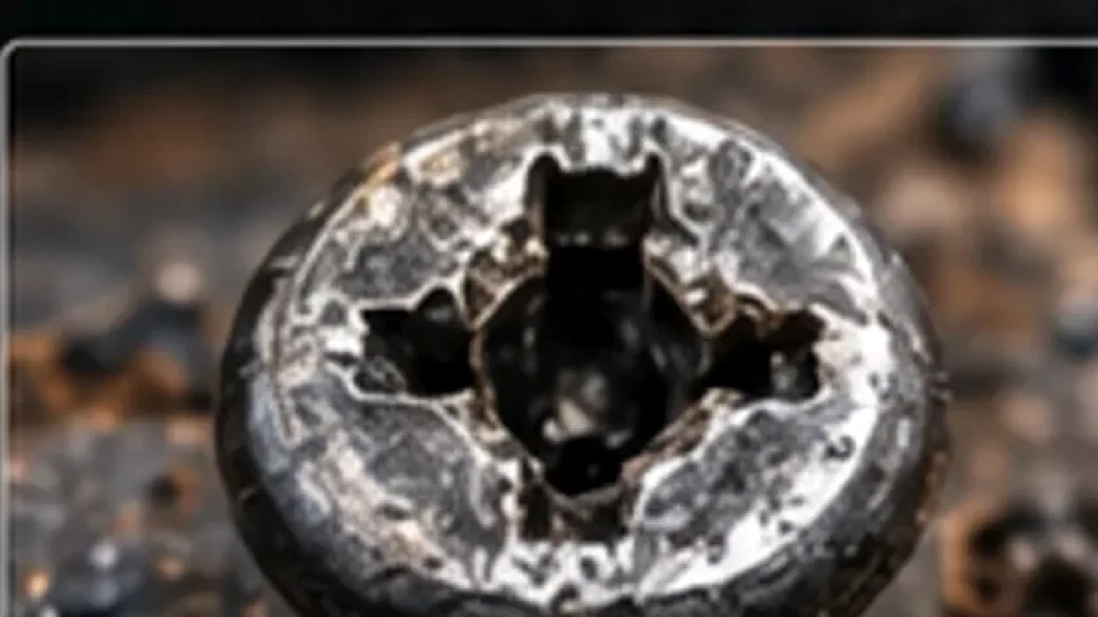

A damaged screw in metal is a torque-transfer problem. The goal is to create a reliable new drive path while removing as little material as possible.
What you’ll need
- correct-size driver or bit
- driver handle with strong axial control
- screw extractor set
- locking pliers
- small rotary/cutting tool where appropriate
- eye protection
Stop before the drive gets worse
Machine screws in metal often combine drive damage with thread friction, corrosion or threadlocker. If the tool is slipping now, more of the same torque rarely improves the situation.
Match the method to the available geometry
For a screw in metal, look at how much drive recess or external head remains and whether the surrounding surface can tolerate cutting, gripping or drilling.
Reduce the torque required
Corrosion, threadlocker, clamp load and damaged threads can all increase removal torque. Address those causes where possible instead of relying only on more driver force.
Step-by-step
Clean and inspect
Remove paint, dirt and loose metal so the driver can seat as deeply as possible.
Try a fresh exact-fit tool
Keep the tool square to the fastener and apply controlled axial pressure.
Create a new way to transmit torque
Depending on access, use external gripping, a cut slot, an interference-fit bit or a dedicated extractor.
Use drilling as a controlled escalation
If the head must be sacrificed, protect the surrounding material and keep the drill centered.
Method comparison
| Method | Best when | Main risk |
|---|---|---|
| Fresh correct driver | Some drive geometry remains | Further cam-out if size is wrong |
| External grip | Head edge is accessible | Crushes or rounds the head |
| Extractor | Centered access and adequate material | Tool breakage |
| Head drilling | Fastener can be sacrificed | Surface or hole damage |
Common mistakes to avoid
Repeatedly using the same slipping driver is the fastest way to turn a partly damaged recess into a completely rounded one. Other common errors are using a worn bit, choosing a size that is merely close, holding the driver at an angle, or jumping straight to drilling when useful head geometry still remains. Reduce the torque required before demanding more grip: clean the recess, address corrosion or threadlocker where appropriate, and keep the driver square. Escalation should create a better torque path, not simply apply more force to a failing one.
After the fastener is removed
Discard a screw or bolt whose drive or head has been seriously damaged unless the application specifically allows reuse and the fastener remains otherwise serviceable. Inspect the mating thread and the seating surface for damage caused during removal. Before installing the replacement, confirm the correct diameter, pitch, length and drive size, then start it by hand. If abnormal resistance returns during the first turns, stop and diagnose the thread instead of using the new fastener to cut through the problem.
How to judge whether the repair is working
A successful repair becomes more controlled as you progress: tools stay centered, the fastener or thread responds without sudden deformation, and each step preserves a clear path to the next option. Stop when the evidence moves in the opposite direction—tool twist, off-center cutting, cracking, missing wall material, rapidly increasing drag or loss of a reliable reference surface. Those signs mean the original repair plan no longer matches the condition of the part.
For high-load, safety-critical, pressure-containing or manufacturer-controlled joints, visual improvement alone is not proof that the joint is serviceable. Use the equipment maker’s inspection, replacement and torque requirements.
Technical decision depth
A damaged drive and a seized thread are separate faults, even when they appear together. First decide whether the screw would probably turn if you could transmit torque to it. If corrosion, threadlocker, paint or mechanical preload is holding the fastener, improving grip without reducing that resistance can destroy the remaining head geometry. Conversely, if the screw is free but the recess is damaged, aggressive heat or extraction may add unnecessary risk. The repair should address both grip and thread resistance in the right order.
Head geometry also controls the method. A proud hex or socket head may allow external gripping. A countersunk screw offers almost no outside purchase but may allow a new slot, a dedicated extractor or head removal followed by shank removal after the clamped part is separated. Recessed fasteners can limit tool angle and make bit seating more important. Use a method that creates a better torque path without sacrificing the surrounding surface, and switch methods when the current one stops improving engagement.
Technical references
Use the instructions for the exact fastener, driver, extractor or repair product you are working with. These references support the terminology and general method choices in this guide.
Protect the geometry you still have
Successful fastener repair is usually about preserving options. Before drilling, cutting or applying more torque, identify which surfaces still provide useful reference: the center of the broken shank, an intact section of thread, the remaining drive recess, or the original axis of the hole. Once that geometry is destroyed, later methods become less accurate and often more invasive.
Use the smallest escalation that addresses the actual failure. Clean contamination before cutting; improve tool engagement before adding leverage; center a pilot hole before enlarging it; and verify thread size before introducing a tap or insert. Between attempts, inspect for new damage rather than assuming that more force is the only next step.
Check the joint before it returns to service
Removal or repair is not the final quality check. Clean chips and debris, inspect the parent material, and verify that the replacement fastener starts smoothly by hand. Match the intended fastener specification, including material or grade where relevant. On safety-critical or highly loaded joints, follow the equipment maker’s limits for reuse, thread repair, torque and replacement. If those limits are unavailable or the parent material has cracked or shifted, professional inspection is the safer outcome.