How to Repair Stripped Threads in Aluminum
How to distinguish light thread damage from stripped aluminum and choose between chasing, re-tapping and inserts.


Aluminum threads fail easily when a bolt is cross-threaded, over-tightened, repeatedly serviced or loaded with too little thread engagement. The repair should match the damage rather than automatically reaching for a tap.
What you’ll need
- thread pitch gauge
- thread chaser set
- thread repair kit
- correct system-specific tap and installation tool
- depth gauge or caliper
- cutting fluid as specified for the process
Do not confuse chasing with rebuilding
A thread chaser can clean corrosion or reform light damage. It cannot replace aluminum that has been torn out of the hole. A cutting tap may make a damaged thread look cleaner while also removing additional material.
Keep the original fastener size when possible
Changing to a larger bolt can create clearance, strength and compatibility problems elsewhere in the assembly. Insert systems are designed specifically to create new internal threads while preserving the original nominal fastener size.
Choose the insert system from the application
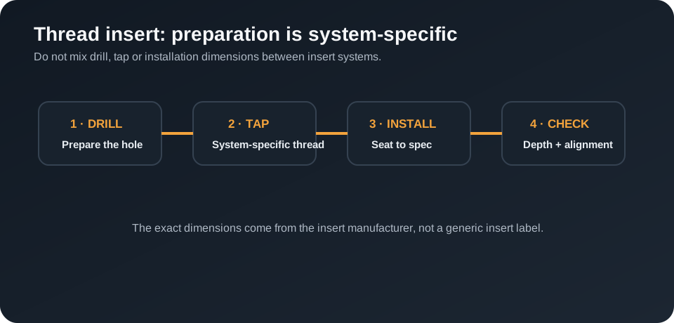
Helical wire inserts and solid bushing-style inserts use different installation geometry and tooling. Follow the manufacturer’s drilling, tapping, depth and installation instructions for the exact system. Do not mix generic drill sizes across systems.
Step-by-step
Identify the original thread
Confirm diameter and pitch from an intact fastener or documentation.
Inspect the damage
Clean the hole and determine whether thread material is deformed or missing.
Chase only light damage
Use a thread chaser when the basic thread form still exists.
Select an insert when material is stripped
Confirm wall thickness, depth and application limits.
Follow the insert maker’s drill/tap sequence
Helical and solid systems use dedicated installation geometry.
Verify engagement and torque requirements
Hand-test the repaired thread and follow the equipment manufacturer’s assembly specification.
Method comparison
| Method | Use it when | Watch for |
|---|---|---|
| Clean / chase | Dirty or lightly deformed threads | Cannot replace missing aluminum |
| Re-tap original size | Minor damage with adequate remaining material | Removes more material |
| Helical insert | Stripped hole with suitable wall thickness | Needs STI tap and system-specific procedure |
| Solid insert | Application favors a bushing-style repair | Larger installation envelope in many systems |
Common repair mistakes
A frequent mistake is treating every rough thread as if it needs a cutting tap. A tap removes material; a thread chaser is intended to clean or reform an existing thread. Other errors include guessing the pitch, starting a tool from a damaged false lead, forcing a fastener through resistance, or judging success only by whether the bolt turns. The repair method should match the actual failure mode: contamination, deformation and missing thread material are three different conditions and should not receive the same treatment.
How to verify the repaired thread
Clean out all chips and debris, then hand-start the correct fastener and confirm consistent engagement through the required depth. Check that the fastener does not bottom prematurely and that any insert sits in the position specified by its manufacturer. For joints with defined torque, clamp-load or safety requirements, visual appearance and smooth rotation are not enough; use the component manufacturer’s approved tightening and repair procedure. If those requirements cannot be verified, do not treat an improvised torque test as proof of repair strength.
How to judge whether the repair is working
A successful repair becomes more controlled as you progress: tools stay centered, the fastener or thread responds without sudden deformation, and each step preserves a clear path to the next option. Stop when the evidence moves in the opposite direction—tool twist, off-center cutting, cracking, missing wall material, rapidly increasing drag or loss of a reliable reference surface. Those signs mean the original repair plan no longer matches the condition of the part.
For high-load, safety-critical, pressure-containing or manufacturer-controlled joints, visual improvement alone is not proof that the joint is serviceable. Use the equipment maker’s inspection, replacement and torque requirements.
Technical decision depth
A damaged drive and a seized thread are separate faults, even when they appear together. First decide whether the screw would probably turn if you could transmit torque to it. If corrosion, threadlocker, paint or mechanical preload is holding the fastener, improving grip without reducing that resistance can destroy the remaining head geometry. Conversely, if the screw is free but the recess is damaged, aggressive heat or extraction may add unnecessary risk. The repair should address both grip and thread resistance in the right order.
Head geometry also controls the method. A proud hex or socket head may allow external gripping. A countersunk screw offers almost no outside purchase but may allow a new slot, a dedicated extractor or head removal followed by shank removal after the clamped part is separated. Recessed fasteners can limit tool angle and make bit seating more important. Use a method that creates a better torque path without sacrificing the surrounding surface, and switch methods when the current one stops improving engagement.
Technical references
Always follow the instructions for the exact drill, extractor, insert or repair system you use. These references support the terminology and method choices in this guide.
Preserve boss wall thickness
An aluminum thread repair succeeds only if enough sound parent material remains around the prepared hole. Before choosing an insert, consider boss diameter, hole depth, alignment and whether enlarging the hole will approach an edge, fluid passage or sealing surface.
Decision checkpoint
After the repair, verify that the insert or restored thread does not interfere with a sealing face, bottom out a bolt prematurely, or protrude into an internal passage. A repair can feel mechanically sound during hand assembly while still changing the functional geometry of the component.
Technical decision note
Technical decision note: In aluminum, thread repair is constrained by the material that surrounds the hole. Inspect boss diameter, wall thickness and remaining thread before choosing a larger tap or insert. A repair that requires more drilling may be mechanically sound in a thick casting but inappropriate near a thin wall or sealing surface. Keep chips out of bearings, passages and assemblies, and verify the insert system’s exact drill and tap requirements rather than substituting generic dimensions.